Networking
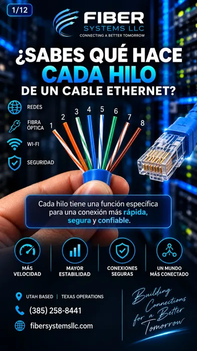
Eight conductors, four pairs: understanding Ethernet cable
The image visually separates the eight conductors of a twisted-pair cable to show their colors.
Read: Eight conductors, four pairs: understanding Ethernet cable ↗FIBER SYSTEMS JOURNAL
Fiber optics, cabling, testing and technology explained through images and individual articles.
20 articles · English and Spanish
Networking
The image visually separates the eight conductors of a twisted-pair cable to show their colors.
Read: Eight conductors, four pairs: understanding Ethernet cable ↗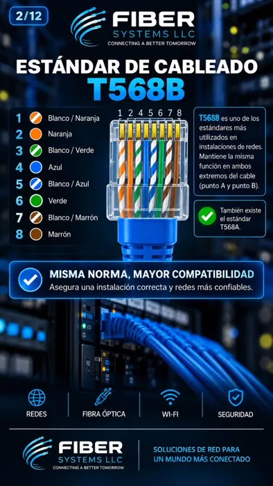
Installation
The infographic shows the color assignment for the eight positions of a T568B termination.
Read: T568B: color order and consistent termination ↗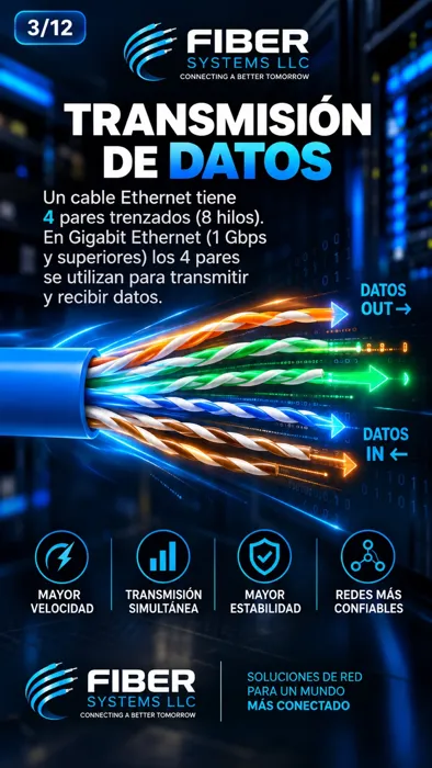
Networking
The infographic represents the four pairs in an Ethernet cable and the movement of data.
Read: How pairs participate in Ethernet transmission ↗
Networking
PoE stands for Power over Ethernet: power and data through compatible Ethernet cabling.
Read: What PoE is and what it changes in an installation ↗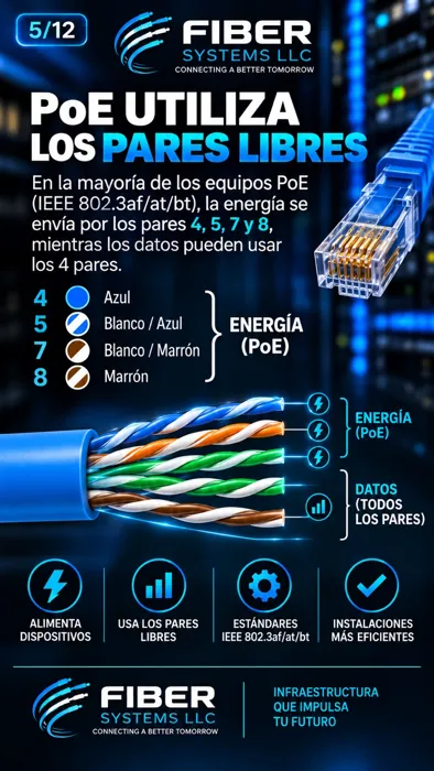
Networking
The image states that PoE uses spare pairs. That statement must not be treated as a general rule.
Read: PoE cable pairs: an important clarification ↗
Networking
The infographic groups IP cameras, access points, VoIP phones and other devices that can receive power over Ethernet.
Read: PoE devices: cameras, Wi-Fi and phones ↗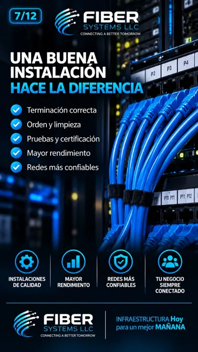
Installation
The image presents blue patch cords organized in a rack and highlights termination, organization and testing.
Read: What distinguishes a well-documented cabling installation ↗
Testing
The image brings together termination tools and test instruments, with a visual pass indication.
Read: Network tools: verification is not certification ↗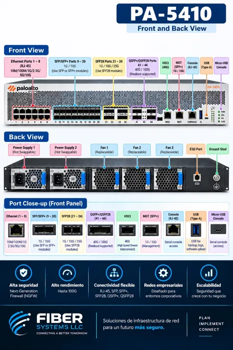
Security
The infographic shows front and rear views of a Palo Alto Networks firewall and identifies connections and components.
Read: PA-5410: recognizing firewall interfaces ↗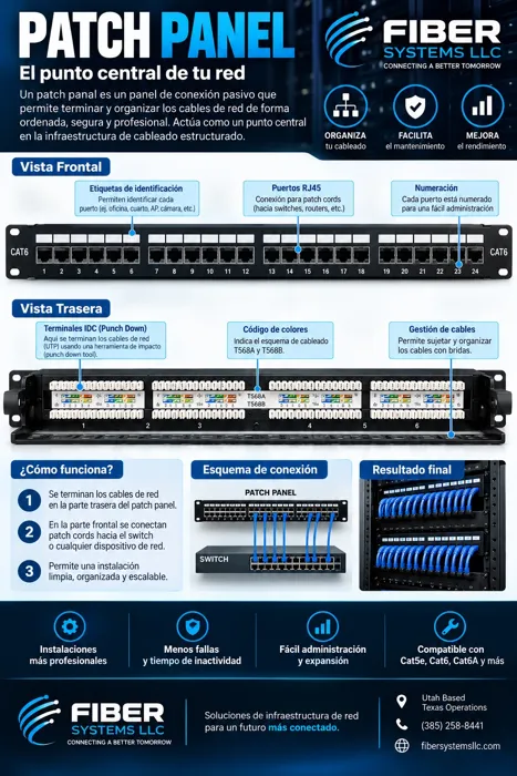
Organization
The image distinguishes front ports from rear terminations and shows a central distribution point.
Read: Copper patch panels: from horizontal cable to switch ↗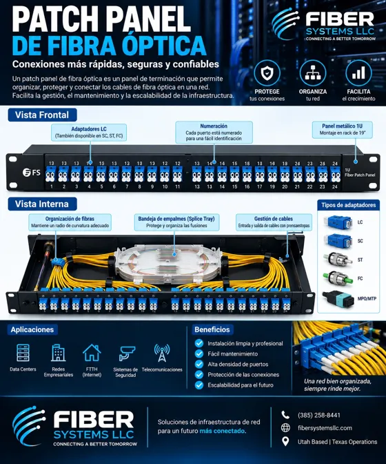
Organization
A panel brings optical connections together at a distribution point that can be maintained and documented.
Read: Fiber patch panels: accessible, identified connections ↗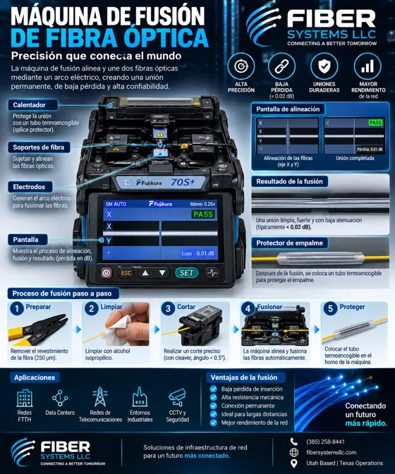
Splicing
The fusion splicer joins prepared fibers; the job also includes protecting and organizing the joint.
Read: Fiber fusion splicing: from preparation to protection ↗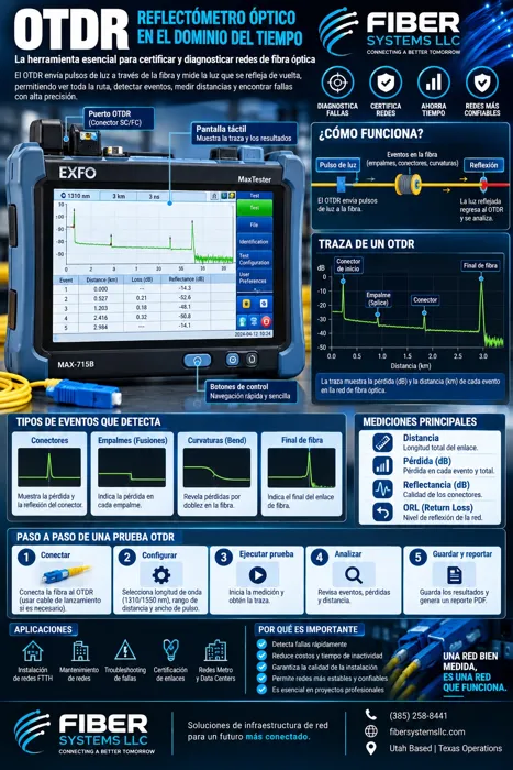
Testing
A trace shows how the measured optical signal changes along the fiber.
Read: OTDR: understanding a fiber link trace ↗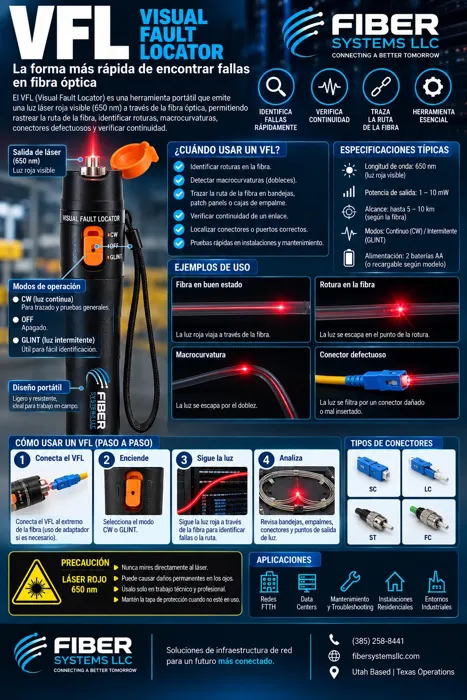
Testing
Visible light helps check continuity and locate some faults in accessible sections.
Read: VFL: what a visual fault locator can show ↗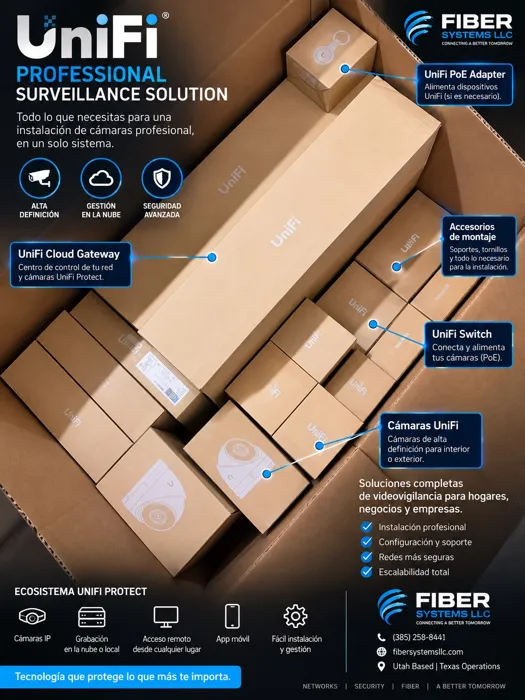
Security
A surveillance system combines cameras, networking, power and recording capacity.
Read: UniFi Protect: the equipment behind a camera installation ↗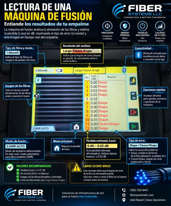
Splicing
Alignment images and machine warnings help evaluate the splicing process.
Read: Understanding a fusion splicer display ↗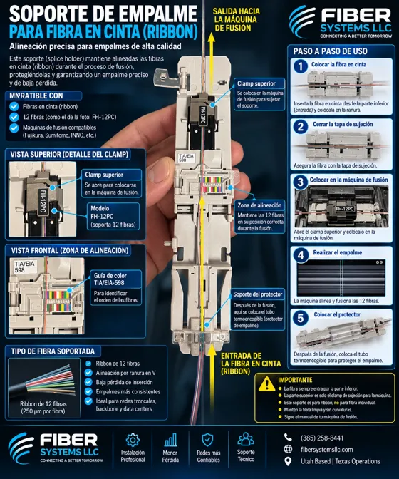
Splicing
A holder keeps multiple fibers aligned during preparation and transfer to the fusion process.
Read: Ribbon preparation and holders for mass fusion splicing ↗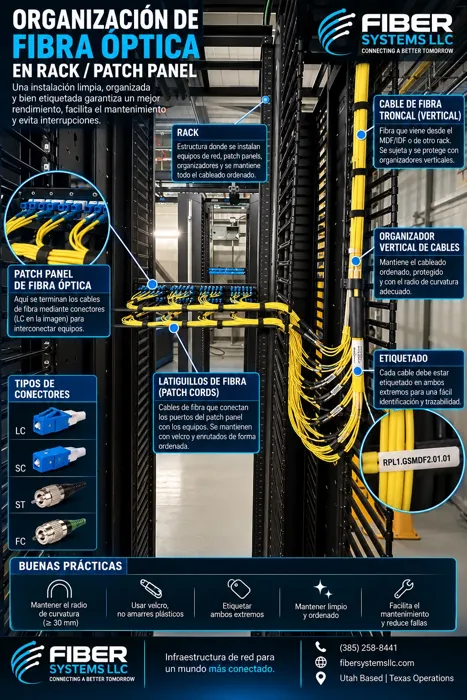
Organization
An organized rack makes connections easier to trace and equipment easier to access.
Read: Organizing fiber in racks and patch panels ↗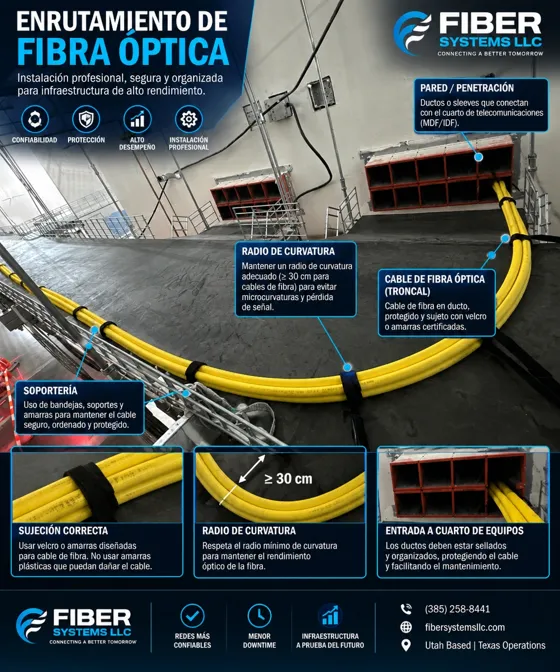
Installation
The cable pathway is part of network design, from the building entrance to the rack.
Read: Fiber routing: pathways, supports and bends ↗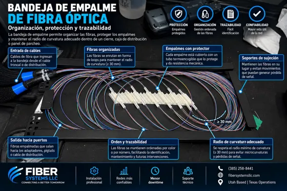
Organization
A splice tray brings fibers, service loops and splice protectors together in an organized space.
Read: Splice trays: organizing and protecting fiber ↗